Extending the Channel Model
A radio propagation channel describes how the environment can affect the radio signal as it travels between the transmitter and receiver. As devices move and signals bounce off of buildings or vehicles, changes in frequency, phase and power occur. Wireless engineers in the industry broadly model these effects with a few main variables such as:
The frequency shift from receiver movement relative to the transmitter.
The strength and delay of multiple signal reflections or bounces.
The amount of separation perceived between two versions of the signal.
In real life we have endless number of different radio channels depending on the environment and the user behavior. In the lab environment we have to limit the testing to a few channel models that can be representatives of all possible real life environments.
NIST channel model by default
Bluetest's reverberation chamber RTS Test System inherently provides a complex multi-path channel environment. The chamber easily supports the published NIST channel model without any external signal conditioning or channel emulator. This model is very similar to pedestrian indoor environments like offices, shopping malls etc. The NIST channel model describes a power delay profile (PDP) that is exponentially decaying, just like what happens in the RTS. The delay profile can be adjusted by changing the amount of RF absorbing material in the RTS. In some cases however, it is desired to create and test with more extensive channel models, especially when testing data throughput.
Examples of alternative channel models
Introduce high speed Doppler shift
Modify the PDP by introducing longer delays as well as multiple delay clusters
Adjusting the channel correlation
UMi-IS and UMa-IS 3GPP/CTIA channel models:
isotropic versions of urban micro and urban macro channel models
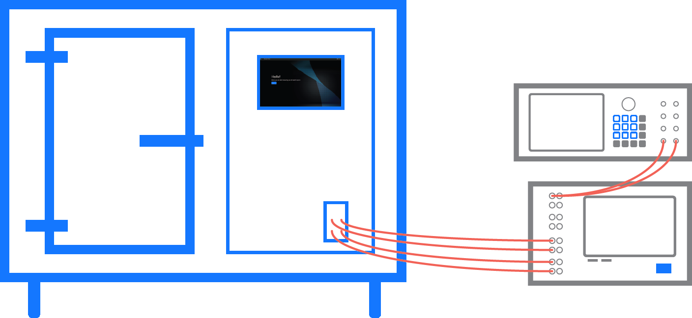
Adding a channel emulator
By adding a channel emulator to the test system, adjustment of these parameters is possible. The channel emulator is connected between the communication tester and the Reverberation Test System and the test procedure is described in 3GPP TR37.977. It is recommended to use at least 4 connections between the channel emulator and the reverberation chamber to mitigate double Rayleigh fading caused by having fading both in the channel emulator and the reverberation chamber. A uni-directional setting can be used in the channel emulator if a separate antenna provides an uplink signal to the communication tester.Working with the world leading partners
Bluetest has been working closely with the leading channel emulator providers and Bluetest Flow measurement software currently supports channel emulators from Spirent and Keysight. Our collaboration has developed an innovative way to provide complex wireless test environments without an overly complex test system. Wide channel variations can be maintained yet the calibration procedure remains very straightforward. The Reverberation Test System environment still ensures:
An isotropic environment with randomized angles of arrival from all 3D spatial angles over a large number of independent field samples
Polarization balance
A full 3D evaluation of the device for realistic MIMO channel conditions
More carriers and higher order MIMO
- testing is more important than ever
Our solution does not stop at one carrier with 2x2 MIMO. With the introduction of LTE-Advanced the number of deployed carriers has quickly increased. Bluetest's reverberation chamber with channel emulators currently supports up to 4 carriers with 2x2 MIMO or 2 carriers with 4x4 MIMO. With the increased complexity that can affect the performance in your device, your testing becomes even more important.