Base station testing - new test challenges with the introduction of 5G
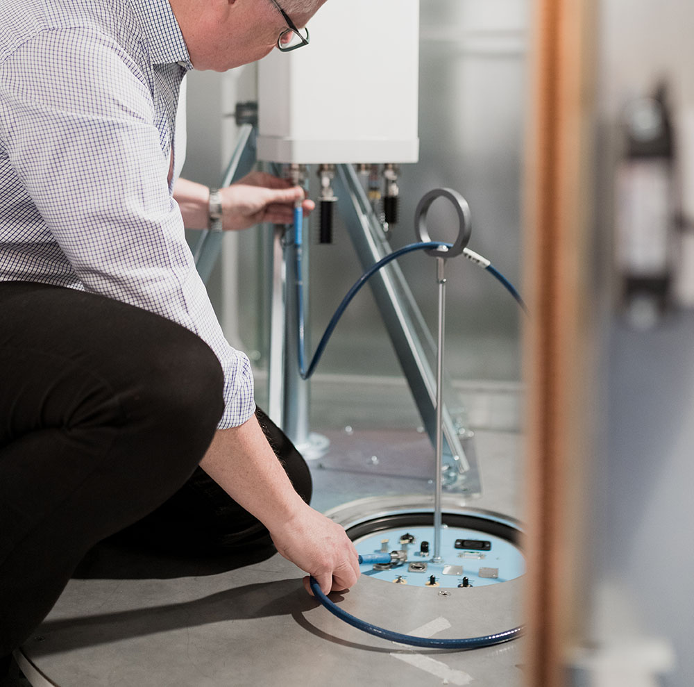
Traditionally base stations have been verified by measuring their performance conductively at the antenna interface. With 5G, we enter a new and exciting era for base station design. Base stations and Remote Radio Units (RRU) are moving towards more integrated antenna/radio solutions, as well as Massive MIMO with 64 or more radio/antenna elements. These Advanced Antenna System technologies are applied also on LTE base stations to improve network capacity as well as reduce power consumption. However, this new breed of base stations will introduce new measurement challenges as these new design considerations change or eliminate the traditional antenna connector interface. Without access to these connectors, the test equipment must measure base station performance after the antenna output in a radiated, wireless over-the-air (OTA) environment.
Types of base stations
The 5G base stations are divided into four categories depending on architecture and frequency range. The 4G base stations with/without an Advanced Antenna System are classified in a similar manner and many of the measurements are carried over from 4G to 5G.
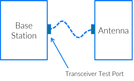
- BS Type 1-C operates in frequencies below 7.125 GHz and has a traditional antenna interface. These base stations can be measured conductively by connecting a cable to the base station antenna interface port.
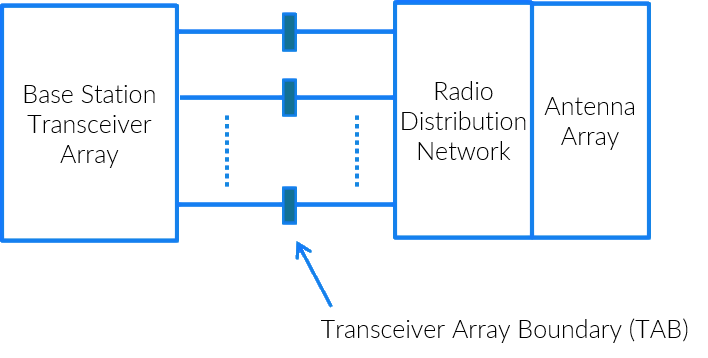
- BS Type 1-H also operates in the sub-7.125 GHz range but the antenna interface consists of multiple antenna connectors connected to an antenna array. The required measurements are divided into conductive measurements and OTA measurements.
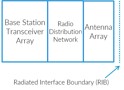
- BS Type 1-O is a sub-7.125 GHz base station where the transceiver and the antenna are fully integrated, hence forcing all measurements to the Over-the-Air domain
- BS Type 2-O shares architecture with BS Type 1-O but operates in the 24.25–52.6 GHz domain and all measurements are defined as OTA measurements.
Over-the-Air (OTA) test challenges
The base station test scope is quite substantial and many OTA test technologies will be needed to cover the full OTA scope in the most efficient way. Managing test time for all test cases as well as chamber investment cost becomes more and more critical, driving metrics like “cost per test case”. Moving test cases, where possible, from slow and expensive test systems to faster and/or cheaper systems, pushes down the overall test costs and increases the overall test capacity.
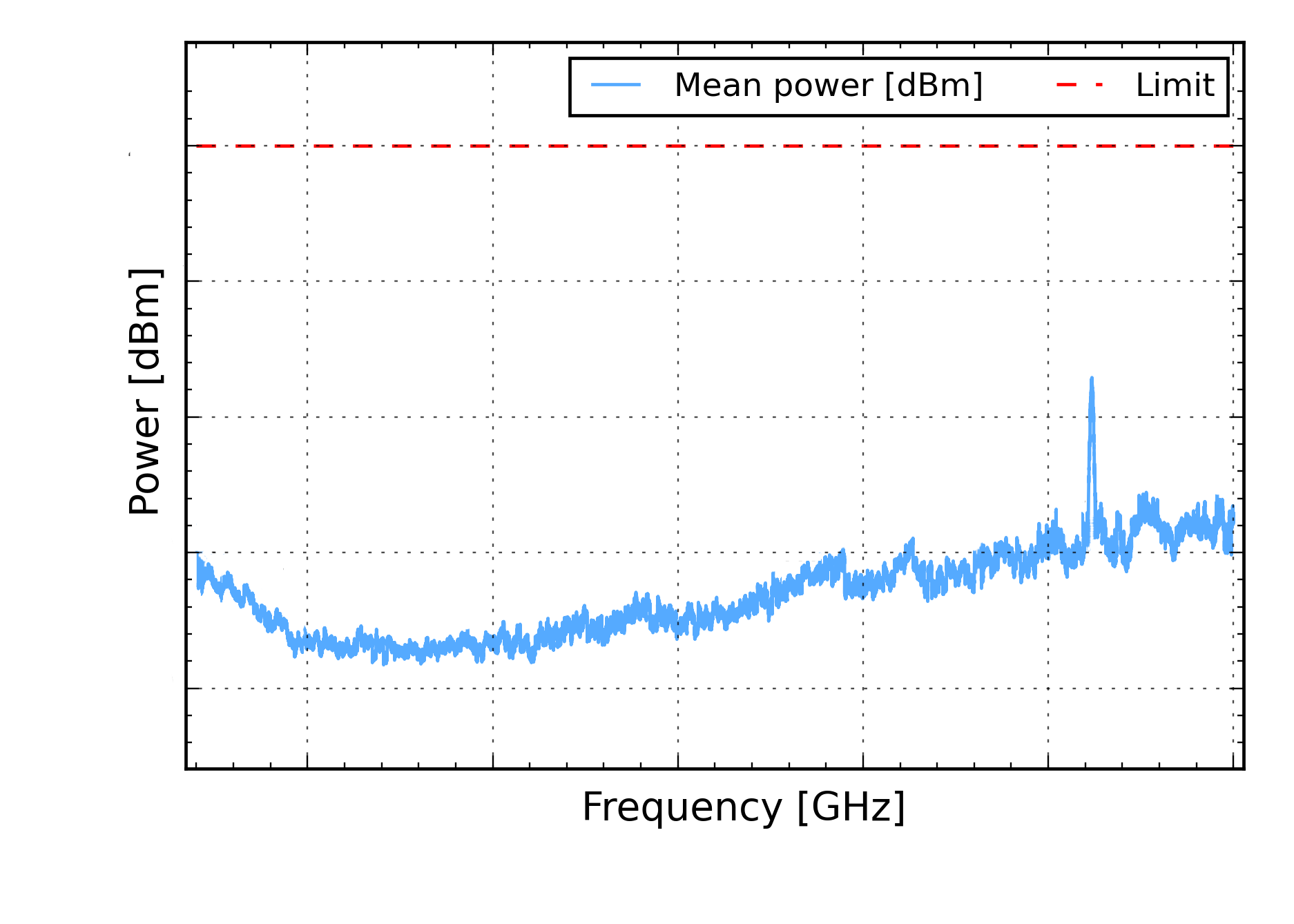
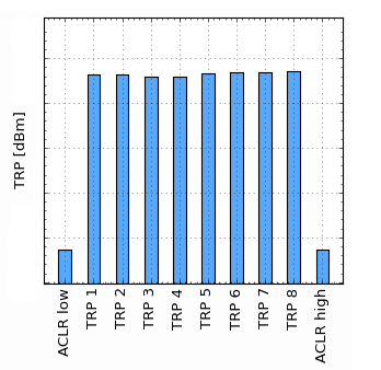
Two of the main OTA technologies are the reverberation chamber (RC) and the anechoic chamber (AC). Both of them are included in the 3GPP NR base station radiated conformance test specification TS 38.141-2 (NR; Base Station (BS) conformance testing; Part 2: Radiated conformance testing) and TS 37.145-2 (Active Antenna System (AAS) Base Station (BS) conformance testing; Part 2: radiated conformance testing). The reverberation chamber is included as test method for TRP-based RF metrics such as total output power, adjacent channel leakage power and spurious emission while the anechoic chamber (including the compact antenna test range) is used for all the measurements where also the directivity information is needed, for example EIRP and EIS.
Measurement uncertainty
The measurement uncertainty is determined by many different components such as contributions from the measurement instruments, calibration method, number of measurement samples and chamber uncertainty. A measurement uncertainty budget can be created by identifying and quantifying all these different contributions to the total uncertainty. Read more in for example the 3GPP specification TS 38.141-2, section 4.1.2.
Link budget
3GPP currently defines measurements up to 60 GHz while FCC has requirements going up to 100 GHz or even higher depending on test object. Regardless of chamber technology the losses will increase over frequency. Optimizing the losses and introducing filters and amplifiers when needed are one of the test system design challenges.
Test time
Test time per test case becomes more and more important, and a challenge, with the increasing amount of frequency bands, standards, bandwidths and other parameters that affects the amount of test permutations. Longer test times translates to the need for additional test equipment and increased cost per test case. The reverberation chamber is usually significantly faster than the anechoic alternatives for 3D power measurements as measurement samples can be acquired continuously, rather than for fixed DUT positions requiring repositioning between each sample.
Other base station measurements in RC
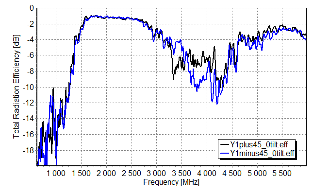
Antenna efficiency
One of the fundamental measurements in the RC is antenna efficiency, i.e. quantifying the internal losses of the antenna. This type of measurement can be executed with very good uncertainty in just a few minutes.
Power added efficiency
The efficiency measurement can be extended also to complex and highly integrated active antenna structures. The total radiated power is measured in parallel with the power consumption, allowing for very detailed analysis of the Power added efficiency (PAE) and optimization of the design.
Correlation and coupling
Another measurement closely related to the design of the antenna solution is the correlation between antennas or antenna elements. A low correlation between the antennas or antenna elements typically contributes to better overall MIMO and beamforming performance.
Error Vector Magnitude
Error Vector Magnitude (EVM) is typically measured in the anechoic chamber but Bluetest has developed a patented method allowing for measurements of EVM also in the faded environment present in the reverberation chamber.
Main advantages of the reverberation chamber
The robust performance of the reverberation chamber makes it is easy to move RF power measurements from the conducted domain to the OTA domain, while still retaining measurement time in the 10s-of-seconds-to-minute range also for higher frequencies and larger frequency spans. The reverberation chamber quickly summarizes how conducted RF power is radiated by the device’s antennas into the external RF environment as isotropic RF power or Total Radiated Power (TRP). Measurement sampling is done over time and fading positions rather than over geometric DUT positions. Chamber uncertainty can, with a good chamber design, be kept low and well within 3GPP requirements also at mmWave frequencies. Bluetests' solution for base station measurements is RTS85HP.
Meeting the expectations from the base station industry, continued innovation for reduced test times and lowered cost per test case remains a commitment for the Bluetest R&D team.